If neither of those of work for you, you can donate any amount by clicking here. |
-
Posts
1540 -
Joined
-
Last visited
-
Days Won
33
Content Type
Profiles
Forums
Events
Downloads
Store
Articles
Everything posted by RIP-Felix
-
Floyd's probably my favorite band if you pin me down to one, but tool is right up there with them IMO (but that one show's my age). Conversely, if you don't think Tool belongs up there with Floyd it shows your age also. Luckily I have a diverse palate for music and don't give preferential treatment to only those bands that defined the decade of my adolescence, like it seems most people do (60s classic rock Dad complaining of Grunge and Rap for instance). While I don't care for Death metal personally, I can hear the musicality. The tempo is just to rapid for my liking + the demonic screaming. I'll admit I did prefer Metallica's Black album because they slowed down, but I like fast metallica too. I don't subscribe to the fast metallica sold out and ruined fan trust with the Black album. That's bull. Widen your musical ear, and grow up! They sold more of that album that the rest, so can you really blame them for widening their appeal? It's their lively hood, don't hate just because they made a financial decision. It worked out for them and all the people who became Metallica fans because of it, like me.
-
That tech said it almost never goes out, so I've been focusing on all the components up to it. If after I replace the chips, and try another RCA cable, with working ones and It still doesn't work, then I may have to crack it open. It's soldered on in such a way you can't open it without desoldering it from the motherboard. I'm at my wits end with this (literally). I can't find/think of anything else to try if swapping the chips doesn't work. If it does, then I should be able to pick up a replacement fairly cheap. I just need to know which one is bad, if any. Like you said, however, maybe it is the RF box. If that's the case, then this CX2600A is a prime candidate for a composite video mod, maybe even an RGB mod! I could always just call it dead and mod the case, but I'M GIVEN HER ALL SHES GOT CAPTAIN! If she's got nothing left to give, then I'll call it and start getting excited for the mod. In the mean time, I'll give the old girl the best care I can muster. PS: It's sad when your Atari 2600 has better healthcare than you do!
-
How about Fix-it-Felix if and when I manage to get this problem sorted? @ClassicGMR I was wondering the same?
-
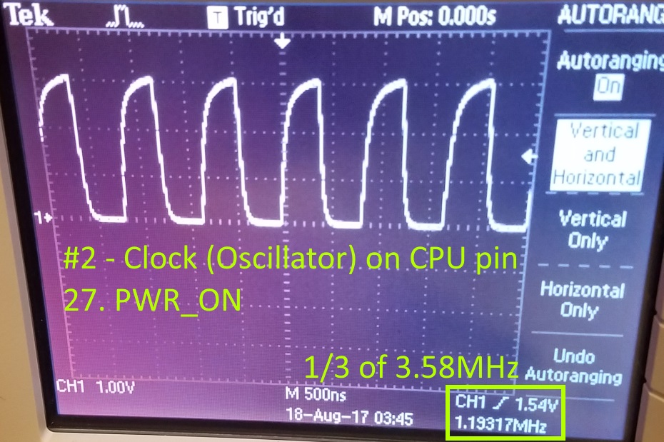
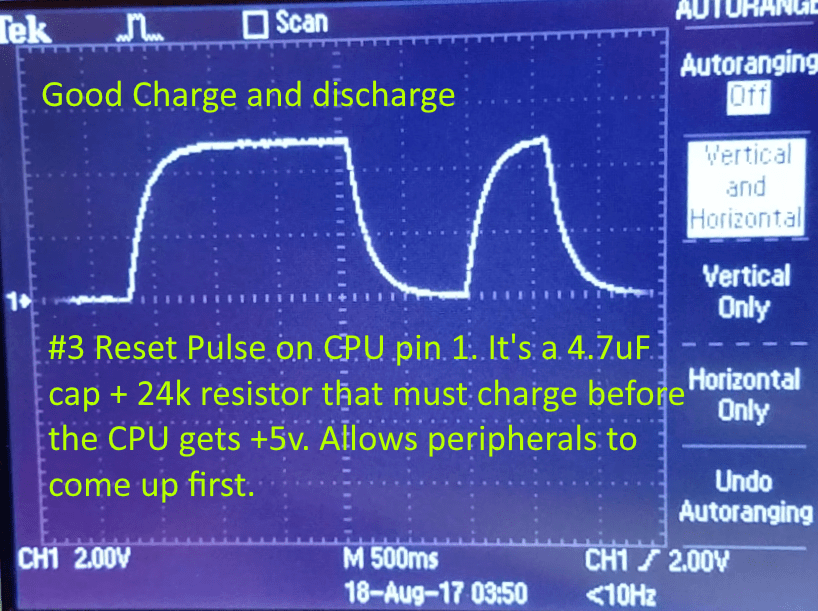
Going Deeper After work today, I stuck around and made use of an oscilloscope to test further. This video helped me immensely: I watched all 10 parts, but this part was what I checked today. Okay, following his methodology: Symptom: Dead unit. It's not sending any video out. I don't get a black screen, it just shows the static like hadn't flipped the on switch. 4 step Test Procedure: Power circuit: With a multimeter I have previously confirmed it's not the power adapter or voltage regulator. I inspected and soldered all cold solder joints (Those I suspected might be). I cleaned the board thoroughly and reseated the chips. CPU Clock (Oscillator): CPU Reset pulse: Replace all three chips: Now this I haven't tried yet. I suspect that because I also confirmed signal patterns on Pin A12, proving the Rom was being accessed and running, I don't actually have a problem with the RIOT or CPU. Maybe it's the TIA or it could be a bad RCA cable, I know it was smashed in the center (I think it got twisted really hard). I'm waiting for another one. I did try a Yellow composite cable, but the tip is a bit long on for the female plug on the motherboard. It went in, but didn't bottom out. No signal, same symptom. Either that's not it, or the composite cable didn't work. The Atari has a heartbeat, I'm just not getting video out. Frustrating! If I had another TIA, I'd try that. But I'll have to wait until the new Atari comes in to test.
-
I thought about getting tickets when they were nearby, but I didn't. I kinda wish I had gone. The other one I regret missing was Tool. I gotta just start living more and going to these things, I just don't like braving the crowds. Sounds like you had a good time, looks fun!
-
Check my edit, it's not what I was hoping. It's weird where projects like this take you. I found the following video. Hardware based handheld Atari 2600 mod, Interesting. Actually there is a useful diagnostic tool at 22:05 I was excited to find. It should allow me to see a voltage High signal on the CPU A12 pin if the cartridge Rom is being accessed. I was wondering since I can't verify the cartridge is working, without video or sound. So I have no idea if the game is actually running. If after turning on the system and A12 stays low (Under 2.4v) then I know it's not getting that far. Kinda fun, I'm really learning the ins and outs of my 2600! Nerd manna: Part 1: Part 2:
-
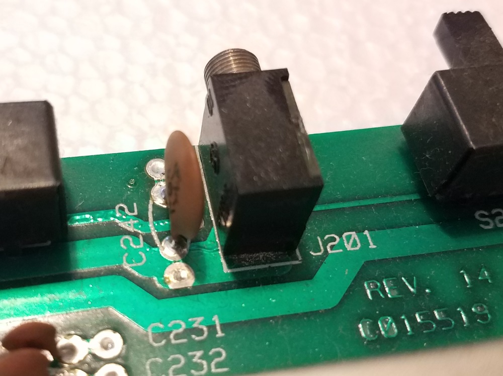
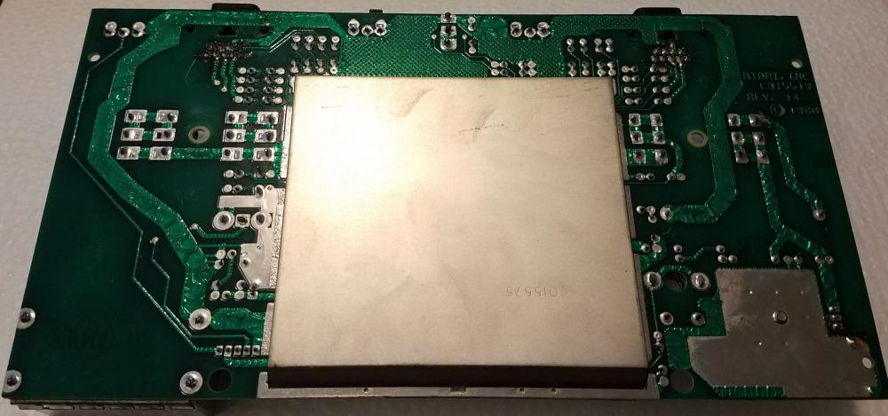
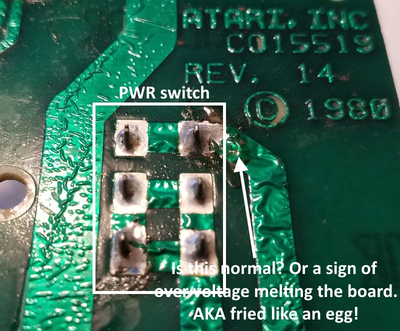
Ok, I found something! As I've been watching that service guide from the 80s I've narrowed it down. I don't have an oscilloscope (at work I have access to one), so checking clock and reset circuit health is more trouble than I care for at the moment. However, he said if it's not the adapter, voltage regulator, capacitor/resistor circuit, then it lies in the chips (CPU, TIA, and/or PIA). But before assuming they're bad to check the solder joints carefully for faults. That's when I spotted this: I'm currently looking up the pins on the schematic of that chip to see what they are. I cant imagine that is supposed to be there. I can't imagine it would have left the factory that way, but this is an old board I picked up at the Goodwill years ago. Who knows what had been done to it before I got it. Still learning more, I'll edit back later... ***EDIT*** OK that it the Television Interface Adapter (TIA). From this teardown site I can see the revision 13 board's backside very well (Mine is revision 14, so the two are very close): It's the bottom row of solder pins. See, no bridging. Something else I've noticed is that the board above has the same wrinkles in the traces! I thought they might be bubbling from melting down my board, but it looks to be a byproduct of the manufacturing process. So that's one mystery solved, and it's a relief. The TIA chip is tasked with converting the digital image to output analog (Color, Sound, and sync). That may very well be why I get no video signal at all. Just plain dead. No black screen. No flickering. No sign that anything is being sent out at all. That's why I originally suspected the PWR circuit, but now I suspect that part is fine. It may just be this chip, assuming the bridge fried it. But who knows, it might work if I just fix fix that bridge. At least I've found a direction! Still learning, I need to see what those pins are. Off to it then (this project is fun)... ***EDIT*** Okay, I think I found my answer. It's not what I was hoping, but it's interesting non the less. Pins 12 and 13 are supposed to be bridged in the NTSC version. If I desolder them, then I would essentially be making a PAL motherboard, I don't know if sticking a PAL chip in it would work, if that's all I could find, but it's an intriguing idea...LOL. The picture from the teardown must have been a PAL board. Rats, I thought I was on to something.
-
I was planning on going with my family and enjoying their classic arcade room, but sadly another arcade closure. I'm sad to see it go http://www.wdwinfo.com/disney-springs/disney-quest.htm#replay This link shows the arcade games they had/have. I wonder what they will do with them? http://disney.wikia.com/wiki/DisneyQuest
-
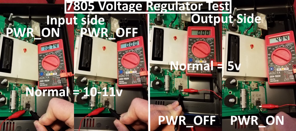
Getting more proactive: Question 1: Does the board have power? Okay, proof that the board is getting power. Load test does indeed drop the Voltage to what I've read is normal. So it's defiantly not the adapter, whew! Question 2: Is the Voltage regulator working? The Voltage regulator is receiving and outputting the correct voltages. So that part is good too. Question 3: Is the Signal getting to the TV? I don't know. It's not when I plug it in strait up. Is the adapter sunk? Maybe, I don't have another to test with. I should go to the local used junk store (Goodwill) to see if I can pick one up. That's where I currently am...off to research more...
-
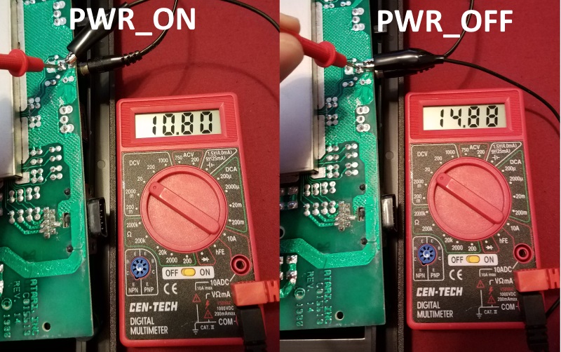
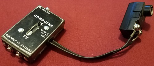
Hmm...post 17 mentions that the Atari voltage regulator can accept anywhere from 8-35V DC and that the adapter will read significantly higher when it's not under load! If 13-14V is normal, I guess that the 15V I was seeing was probably fine. Weird, but okay, maybe that wasn't my problem. Maybe I'll try it again now that it's all cleaned. Who knows, maybe the power contacts were too dirty or the RCA was unseated. Let me plug it in and see if I can't get it running (Crossing my fingers). I'll edit back with the results... ***EDIT*** No dice . Dang, I thought maybe it would work. Well I don't know. I thought maybe it's the RCA to antenna adapter I have. I had another Coaxial to 2-prong antenna adapter. So I tried putting that on the end of the RCA adapter, but it was even looser than the first. Maybe the Atari is outputting a signal, but the adapter is busted, IDK. I don't have another one to test with and haven't used it for anything else since the Atari stopped working. I guess I'll keep looking at guides for ideas of things to try while I wait for the 4-switch "Vader" to get here.
-
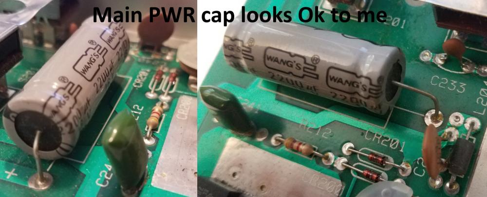
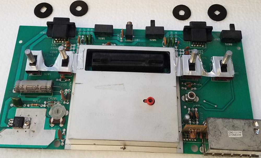
Thanks for the link, I found a few guides, but that one is indeed top notch. I cleaned the board today with 70% isopropyl alcohol, I have a liter spray bottle of the stuff (Very useful to keep around. Did you know you can spray roses and other plant's leaves to kill scale and aphids? And it's nice for the occasional electronics project too;). Anyway, the contacts looked much better. The dark scoring was indeed crud and came off. All the winked traces are still there, but I'm not sure if that was due to 1980s manufacturing process, or has happened since. I have seen similar wrinkled traces in pics of other motherboards, so maybe that's normal. Sorry no pics. I tested with a Multimeter and was able to get continuity all around the board's common layer. The power switch's line appeared contiguous. I went ahead and re-soldered the PWR switch and the Barrel jack contacts adding a bit of new (leaded) solder. That should ensure power is getting to the board. I confirmed good continuity with the multimeter. I also went at the RCA connector and switches with fine sand paper to knock the corrosion off. I tested the RCA with my multimeter and confirmed continuity. So the Atari has power and a good signal out now. I inspected all the caps and other components carefully and didn't see any obvious signs of damage. No bulging, scorching, leaking, unseated chips, or broken solder joints. I'm feeling better about it's chances of survival now! I gave the case a bath and dried everything. I put it back together and I'll let it sit until I get the other one in so I can test it with a working Power supply. I'm not plugging it in until I test the voltage. I'm not trusting 37 year old AC/DC adapters ATM. Damn has it been that long? lol! One thing I haven't done yet, because I just found that link @ClassicGMR linked, is open and clean the switches themselves. I'll have to open it again, but oh well. I'd Better do it right! Although I didn't buy it for this purpose, I do have some Super Lube Silicone Lubricating Grease. It says it has High Dielectric strength and is thermally stable. I think it will work fine for coating the contacts in the switches. I originally bought it to lubricate the guide rods on my 3D printer. It's a huge tube, I'm kinda glad I've found another use for it. Off to it then...
-
The above is just to tease a Raspberry pi NFC project I'm excited about making, if I get around to it. It will combine the above with NFC carts too. This will not be original work, someone else is working on a design of the US version in the facebook group. I'm waiting on his 3D models to be finalized, he's nearly there. I'm going to use the same kit as NEStalgia for "SNEStalgia". I'll have to rework the Power switch, but that's a very minor thing. I haven't decided if I'll do both the US and Euro version of the case, or just the US. I grew up with the US, so that's a must, but I do like the Pal version's ascetics better (Or I would have if I hadn't grown up seeing the US version). So, I may DL the above files from Thingiverse and modify it for NFC. Thoes SNES 8BitDo controllers will be great for these no?
- 112 replies
-
- nes classic
- retropi
-
(and 3 more)
Tagged with:
-
It looks fried to me, but If I can get it working again I would like to keep it. If not, then it's a future modding project candidate for sure. Like yours maybe! I'm looking at a light sixer on ebay at the moment, says it working ($35). I might take a chance on that, I like the look better than the four switch anyway. I wish people would take them apart and provide pics of the motherboard traces...lol. Not going to happen! ***EDIT*** I went ahead and bought a vader black 4 switch on ebay ($50 shipped). It was a decent price, compared to other listings, and the company looks legit; they will refund it if doesn't work. So I guess that means I can use the fried? one for a mod. I'll have to give it some thought. I still might try fixing it.
-
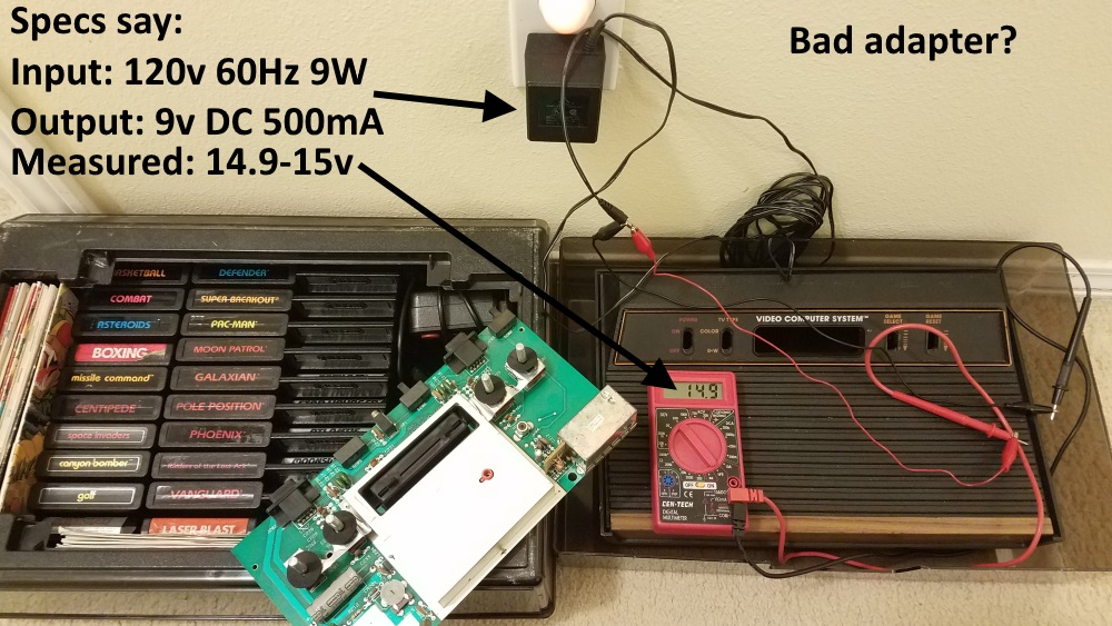
Anyone out there who has fixed an Atari 2600? I haven't cleaned the board yet. I'll try that to see if the dark crud around the PWR switch is just flux that never got cleaned off. If not, I wonder if I can try scraping the trace and soldering over it to reestablish a connection. I'll test with the multi-meter after I clean it to see if it's broken, otherwise I may have to try this. I've read the Atari can handle voltage over 9v, but I don't know if that 15v reading is normal or due to a fault and way too much for the Atari's over-voltage protection to handle. Does this board look fixable, or do I have a fried egg? If so, this may be my next MiniITX case and GameEx rig
-
Oh, now that is tempting. Yes indeed! Thanks for the heads up! Actually the thumb sticks look like they will solve one problem I noticed with the NES30 pro, the PS4 style circles should make it easier to control the Thumb stick and click L/R 3. They also look wider, and will thus fit my fat thumbs better. The shoulder buttons look better, but I'm wondering now if those two circular buttons on the face below the D-pad and Buttons are where they moved L2 and R2? If so, that would make sense. They are not used much, so why detract from the feel and ascetic of a SNES controller? I like it a lot. I think I'll get one too.
- 112 replies
-
- nes classic
- retropi
-
(and 3 more)
Tagged with:
-
In that pi control video, second half, he mentions/shows slider controls for the fan. It's plugged into the +5v rail, so you need a 5v fan, no biggie. Pi control has one slider for the CPU high temp (when the fan kicks in), low temp (When the fan kicks off), and the poll interval. You can set them to your liking. It's very easy. The mosfet I think, were for fan control. It ramps the fan speed up, but it's been awhile since I specifically dove into the technical aspects of the hardware. I'm a bit rusty and may be speaking out my butt. I'm really liking the NES30 pro! At first I had some trouble getting it to stay paired, but then I saw that video I posted, and it solved my problem. Now, for the most part, it will pair every time without much difficulty. I have had to manually remove and re-register it once, but to be fair I was messing with a lot of settings and updating packages. So, it was probably related more to that. Before It would never reconnect, I had to repair in Bluetooth settings after each reboot, which made me unfairly critical of the controller. Now, I love it. I haven't paired another one to see if the leds change color, but I know you can pair multiple devices. The color of the leds do indicate what mode the controller is in however, so they may not want to change them for player 2 lest he/she incorrectly think they accidentally put it into android mode or something. They just get added to the Bluetooth registered device list by MAC address. I imagine you could have 4 easily. I'd look it up on YouTube to see if they change color if your interested, but I don't know. I will tell you that it's not the most useful for N64, I don't really like where the z button is on the shoulder. It works ok though, having all the button you need to play 12 button games. It's more comfortable than an NES controller, shoulder buttons are harder to use than a SNES, but has similar feel otherwise. The buttons are stiffer than SNES, but satisfyingly so if that makes sense. I noticed playing asteroids that the d-pad is a bit sensitive. Pressing up to thrust away from an incoming roid had the annoying habit of simultaneously turning left or right, so I had to be extra careful to press perfectly up. It's less forgiving than a NES or SNES in that regard. The thumb sticks are quite good for such a small controller. They have good sensitivity and spring, maybe not as much travel as I would like and the left one should be transposed with the D-pad, but that would detract from the aesthetic. So I'll not hold that against it. It's still new, so maybe it will loosen up with use, only time will tell. No rumble. Battery life is about a short as a PS4, I'd like it to be better, but it's good for a long session if kept charged in between. Overall, 8bitdo nailed it IMO. My major gripes are mostly preference and concessions made for ascetic/NEStalgic reasons. I'm good with that.
- 112 replies
-
- nes classic
- retropi
-
(and 3 more)
Tagged with:
-
Yup, it a pretty good group of builders on the facebook group. Actually they're being knocked off now! Some douche bag took Evan's designs and reshaped them. Now he's selling for over $100. Oh, and his software install instruction link directly to Evan and Jared's script! WHAT A DICK! I'd put a link to his website so you can see his bad english translation, but I don't even want to give him the free publicity. Frick'n leach! There are a number of other kits available too. You should check out the OSH park PCBs (Here and Here) (you can DL the PCB files and open in eagle). All the parts are linked in the PDF on their Gethub page. Pi control gives you nice control of fan thresholds, a convenient way to upload roms, and write to NFC tags. You can edit the script to add functionality if you want. It's a great starting point for further development I would think! Plus Evan and Jared have opened it to everyone for free without limitation, they don't care if you sell, or even need credit, as long as you don't try to pass it off as your own original work. As for seeing the final product in action, well. I don't have a youtube account and don't particularly want to start one. So, I tend to just post other peoples content to show off the system capabilities. So just pics of my actual system, plus the videos others have made for now. You can get a pretty good idea of how it works. I haven't tried to upload an MP4 video on the forum, I wonder if that'll work?
- 112 replies
-
- nes classic
- retropi
-
(and 3 more)
Tagged with:
-
Part 7: Software Theme: While I liked the one above from @SIMPLY_AUSTIN, I haven't seen any updates and I'm not sure if they're coming. SO alternativly, I like this one (LINK). It's a more traditional variant of carbon, but looks very nice to my eye: This update requires the latest Emulation station update and I went ahead and updated all my Rasbian packages just to be safe. The Theme is just cool! I love the pixelated design and it complements the NES case design. I can't forget I'm playing on NEStalgia vs. any other retropi build. Sure, anyone can use the theme, but combined with my case, it all works together to sell the look! Speaking of looks, I made a new case: I liked the look of Red on Black better than the original colors and was never happy with the way the original case's finish came out. This one came out better (Bondo, sand, prime, sand, prime, sand, prime, sand, and finally paint). However, I made a few mistakes (smudged some wet silver paint). I decided that Silver trim looks better than the Black in the picture, but I got too excited and some wet paint transferred to the black. I wiped as much off as I could, but some remains near the USB port's bottom edge. I'm having trouble getting the silver trim right (so I shelved it for later). I actually redesigned the trim with slots so I can interchange the trim pieces. I'm content with it the way it is for now. Moving on to the NES30 Pro controller installation. I found the following video very helpful. I still sometimes have pairing issues, but I can just plug it into the USB port and repair Bluetooth when that happens. Annoying but It's not terribly inconvenient: I do really like this controller. It feels NEStalgic, but retains all the buttons of a major console. It feels well made and not cheap at all! The only gripe I have is that when playing Super Mario 3 on NEStalgia vs. my NES on CRT, the Lag is noticeable and annoying. I prefer to play on the NES for this reason, but it's why I keep a CRT around anyway. This is probably because of my LCD TV, even though I turned off the advanced features and put it into "Game" mode, and has little or nothing to do with the controller or Retroarch. So, I'm just going to have to live with it unless I get a TV with a lower Latency . ***EDIT*** I wonder if I try the AV out port on my CRT if the lag is improved? I'll see if I can find the AV cord and edit back with the results...***EDIT*** For some reason I can't get anything to display. Just a staticy black screen. I couldn't sort it out so I moved on. Project Cost = $180 (Not including the 3D printer and unused electronics): 3D printed Case and other needed parts = $3 of plastic (Will cost more if you use a service to print for you, like $20) Electronics Kit = $50 Electronics not included in the kit, but needed to complete (RPi3 rev.b, NFC reader, NFC tags): $67.16 4 cans of spray paint (Primer + 3 tones) = $16 8BitDo NES30 Pro Controller (Optional) = $43.95 Where I'm currently stuck: For some reason, when I scrape artwork the changes never stick. If I press select on an individual game and scrape it manually, it wqill only save the metadata if I restart. I tried doing the same after a complete automated scrape and I didn't work. I'm still trying to sort that one out...
- 112 replies
-
- nes classic
- retropi
-
(and 3 more)
Tagged with:
-
Part 6: First Major Challenge - Hardware Before I got started on software, I wanted to tackle the hardware. This is where I hit a knowledge wall. While I've created small electronics projects before, and am reasonably comfortable with soldering, I underestimated the level of difficulty. As I looked into this further, it become increasingly beyond my level of comfort with electronics. I am willing to learn, but I didn’t feel comfortable continuing with my own solution. While Daftmike mentioned a few bits of hardware briefly in one of his videos, he made no attempt to explain the electronics. Instead he started selling kits, then dropped off the face of the planet! I was thinking of getting one of his kits until I read comments on his blog about his disappearance. Then people started getting refunds from PayPal! That's when I read about the Mini NES Builders Facebook group dedicated to continuing the project. FACEBOOK? Yes, that dreaded thing I’ve been avoiding like the plague. I avoided the group as long as I could, but there was nothing besides Daftmike’s videos and what little I could gather from his blog posts. So the Facebook group was my last option. Damn…sigh…It had pictures and wiring schematics. That was it, I gave in and signed up. I started down the path of gathering info on the electronic schematics and even wired my Arduino to a breadboard to begin testing. Then electronic kits began appearing. I quickly decided it would be easier to wait for a kit to become available and go that route instead. So I got on Batch 1 of Evan Wright/Jared Kirchgatter's kit. It wasn’t bad at all ($45 + $5 shipping to USA = $50 total). I got a Non-NFC style A kit, since I already bought my NFC earlier and like the look of the style A USB better. Here is a video they made: Here are a few more videos: Evan and Jared were kind enough to provide a (link) to their complete open source installation and software instructions. They got burned out on making these kits themselves shortly after batch 1 and decided to include a DIY PDF which links the required parts and PCBs you need to build your own, they're not that hard to make! However, since I was one of the lucky few who got in on B1 of their kit, I was able to avoid doing it myself (Bonus Lazy points)! These were much appreciated and are great for any RPi based project! I installed the software and confirmed it was working, but then Life and work derailed the project…Fast forward to now...
- 112 replies
-
- 1
-

-
- nes classic
- retropi
-
(and 3 more)
Tagged with:
-
.jpg.44da0172a400adb6811f03be15189781.thumb.jpg.4316d89cc7dd35bcdf11c619d81a9d25.jpg)
Battle Damage - Unofficial Star Wars Hype Thread
RIP-Felix replied to tthurman's topic in Social Club
404 here How about this one instead? I hope those hot heads are no stupider than WOPR. Lets NOT play the game of Global Thermonuclear War... ...please -
.jpg.44da0172a400adb6811f03be15189781.thumb.jpg.4316d89cc7dd35bcdf11c619d81a9d25.jpg)
PinKadia! The Ultimate virtual Pinball / Arcade / PC combo cabinet!
RIP-Felix replied to TerryRed's topic in Gamer Rigs
Oh the humanity! -
I'm glad the guy was happy with his purchase, but it's not like it's anything revolutionary. I'm underwhelmed. Cardboard and a USB x-input fighting stick + USB C Adapter. What's so exciting about it?
-
I played up to adventure and lost interest. SNES original and the N64 remake were my favorites, but 64 is my favorite of the two by far. Multiplayer mode with my friends was the best. Adventure was an interesting Idea, but it confused me. I didn't feel like it belonged in the StarFox universe, now I know it wasn't supposed to be a StarFox title at all. To me, StarFox is a stoic rail shooter. It's a genera that doesn't leave much room for innovative sequels. StarFox had so much success on SNES and N64 that Nintendo got greedy and tried to make it what it wasn't - a franchise. To me, it's one of the great stand alone rail shooters and shouldn't have to bear the insult of genre infidelity. It is what it is, and that's what I liked about it. I'm fine with HD remakes and even sequels within the rail shooter genre, but the 3rd person shooter, adventure, and strategy genre shenanigans needs to stop.
-
I hope she's doesn't follow your posts! Or maybe you don't care? In that case, the dog comment makes more sense...lol.


